Connection Diagrams Are Also Called Wiring Diagrams. They use images of the components and their. These will usually be drawn in. Wiring diagrams, also called connection diagrams, however, do show how equipment is laid out and the connections. A wiring diagram is a graphical representation of the actual connections between devices and wires used to better comprehend an electrical system. Wiring layout diagrams, also known as connection diagrams, are used to illustrate how components and devices are interconnected within a system. Wiring diagrams, also known as pictorial diagrams, provide a more realistic representation of the physical connections between components. Wiring diagrams, also known as electrical diagrams or schematics, show the physical layout of electrical components and their connections within a system. A home wiring diagram, for. The idea of the electrical or wiring diagram is to trace the flow of power and signals between the sources, control devices, and final loads. The wiring diagram (figure \(\pageindex{2}\)) shows the relative layout of the circuit components using the appropriate symbols and the wire.
from opentextbc.ca
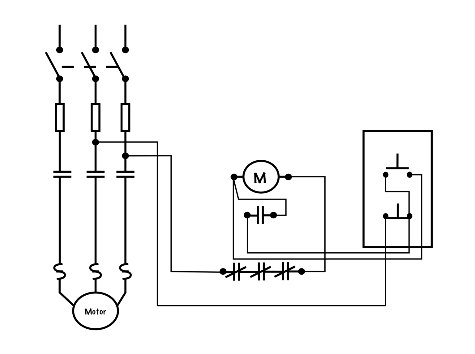
Wiring diagrams, also known as pictorial diagrams, provide a more realistic representation of the physical connections between components. A wiring diagram is a graphical representation of the actual connections between devices and wires used to better comprehend an electrical system. The wiring diagram (figure \(\pageindex{2}\)) shows the relative layout of the circuit components using the appropriate symbols and the wire. Wiring diagrams, also called connection diagrams, however, do show how equipment is laid out and the connections. These will usually be drawn in. Wiring layout diagrams, also known as connection diagrams, are used to illustrate how components and devices are interconnected within a system. They use images of the components and their. Wiring diagrams, also known as electrical diagrams or schematics, show the physical layout of electrical components and their connections within a system. A home wiring diagram, for. The idea of the electrical or wiring diagram is to trace the flow of power and signals between the sources, control devices, and final loads.
Schematic vs. Wiring Diagrams Basic Motor Control
Connection Diagrams Are Also Called Wiring Diagrams Wiring diagrams, also known as pictorial diagrams, provide a more realistic representation of the physical connections between components. They use images of the components and their. These will usually be drawn in. A home wiring diagram, for. The wiring diagram (figure \(\pageindex{2}\)) shows the relative layout of the circuit components using the appropriate symbols and the wire. Wiring diagrams, also known as pictorial diagrams, provide a more realistic representation of the physical connections between components. Wiring diagrams, also known as electrical diagrams or schematics, show the physical layout of electrical components and their connections within a system. Wiring layout diagrams, also known as connection diagrams, are used to illustrate how components and devices are interconnected within a system. Wiring diagrams, also called connection diagrams, however, do show how equipment is laid out and the connections. A wiring diagram is a graphical representation of the actual connections between devices and wires used to better comprehend an electrical system. The idea of the electrical or wiring diagram is to trace the flow of power and signals between the sources, control devices, and final loads.